 " alt="Article Image" class="w-full h-full object-cover">
Are you facing erratic performance from a brushless DC (BLDC) motor, or do you need to verify the integrity of a new one? Testing a BLDC motor effectively is crucial for troubleshooting, quality assurance, and ensuring optimal system performance. Unlike simpler brushed motors, BLDCs require a more nuanced approach to diagnostics.
To test a brushless DC motor1, you primarily check the continuity and resistance of its stator windings, verify the functionality of Hall effect sensors2 (if present), perform an unpowered spin test for bearing integrity, and finally, conduct a powered no-load run to assess smooth operation3 and current draw4.
In my engineering career, troubleshooting motors has been a frequent task, vital for maintaining the complex machinery I design. A faulty motor can mask itself as a controller issue, or vice versa, leading to frustrating and time-consuming diagnostics. My approach has always been systematic, breaking down the problem into logical, testable steps, much like I would approach a complex circuit board. Testing BLDC motors, while seemingly daunting, follows this same principle: isolate, test, and diagnose.
What Are the Basic Steps for Testing BLDC Stator Windings?
The stator windings5 are the heart of a BLDC motor, responsible for generating the magnetic field that drives the rotor. Any fault within these windings can lead to partial or complete motor failure. Knowing how to quickly test them is a fundamental diagnostic skill.
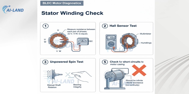
To test BLDC stator windings5, first disconnect the motor from its controller. Then, use a multimeter6 to measure the resistance between each pair of phase wires, ensuring they are equal. Additionally, check for continuity between each phase wire and the motor casing to detect any unwanted short circuits7.
Before you begin any electrical tests, always ensure the motor is completely disconnected from its Electronic Speed Controller (ESC) or driver. This prevents accidental power activation and protects your multimeter6.
The primary test for the stator windings5 involves checking phase-to-phase resistance8. A BLDC motor typically has three phase wires (U, V, W, or A, B, C) that connect to the stator windings5.
- Set your multimeter6 to the lowest resistance (Ohms - Ω) setting.
- Measure the resistance between phase U and phase V.
- Measure the resistance between phase V and phase W.
- Measure the resistance between phase W and phase U.
For a healthy BLDC motor, these three resistance readings should be very close to each other – ideally identical or within a very small tolerance (e.g., less than 5% difference). Low-resistance motors (common in high-power applications) might show readings close to 0 Ohms, but the key is consistency. A significant difference in any reading indicates a problem like a broken winding (open circuit – infinite resistance) or a shorted winding (lower resistance). I always look for balance; imbalance is a red flag.
The second crucial test is to check for phase-to-ground (casing) shorts. This verifies that the winding insulation has not broken down, allowing a wire to touch the motor's metal casing.
- With the multimeter6 still on the resistance setting, place one probe on a metallic part of the motor casing (ensure it is bare metal for good contact).
- Touch the other probe to each phase wire (U, V, W) individually.
- Repeat for all three phase wires.
You should ideally see an "open circuit" or infinite resistance reading for all these tests. Any measurable resistance indicates an insulation breakdown9 and a short circuit, which would likely cause the motor or its ESC to fail if powered.
Here is a summary of the winding tests:
| Test Type | Multimeter Setting | Connection Points | Expected Result | Indication of Failure |
|---|---|---|---|---|
| Phase-to-Phase Resistance | Ohms (Ω) | U-V, V-W, W-U | Three readings should be nearly equal (e.g., 0.1-1.0 Ω) | Significant difference (open or shorted winding) |
| Phase-to-Ground Resistance | Ohms (Ω) | Each phase wire to motor casing | Infinite resistance (open circuit) | Any measurable resistance (insulation breakdown9/short) |
These simple multimeter6 tests are often the first steps in diagnosing a BLDC motor problem. They can quickly rule out common internal winding faults10 without needing complex equipment. (https://en.wikipedia.org/wiki/Blocked_rotor_test)%%%FOOTNOTE_REF_11%%% to observe vibration and listen for unusual noises.**
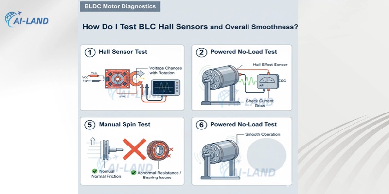
Testing Hall effect sensors2 is crucial for sensored BLDC motors. These tiny sensors detect the rotor's magnetic poles and tell the ESC where to send power.
- Locate Sensor Wires: BLDC motors with Hall sensors typically have 5 small wires: +5V, GND, and three signal wires (often labeled H1, H2, H3 or A, B, C).
- Apply Low Voltage: Connect the +5V and GND wires to a low-voltage DC power supply (e.g., 5V from a regulated bench supply or even a USB port, being careful not to overload).
- Monitor Signal Wires: Use your multimeter6 (set to DC Volts) to measure the voltage on each signal wire relative to GND.
- Rotate Shaft: Slowly rotate the motor shaft by hand. As you rotate, you should see the voltage on the signal wires toggle between High (close to 5V) and Low (close to 0V) in a specific sequence. All three signal wires should switch properly. If a sensor fails to toggle, it is faulty. This sequence needs to be clean and distinct.
Parallel to electrical testing, a mechanical spin test12 is essential. Disconnect all electrical connections and spin the motor shaft by hand.
- Smoothness: The shaft should spin freely and smoothly, without any grating, resistance, or binding.
- Noise: Listen for any unusual noises – grinding, crunching, or rattling – which often indicate worn or damaged bearings.
- Play: Gently try to wiggle the shaft from side to side and up and down. Excessive play indicates worn bearings. This simple test can quickly reveal mechanical issues that no electrical test would detect. My golden rule: if it does not spin smoothly by hand, it will not run well under power.
Finally, for a complete picture, perform a powered no-load test11.
- Connect the motor to its intended ESC/driver.
- Ensure no propeller or load is attached to the shaft.
- Carefully apply power and slowly increase the throttle.
- Observe: The motor should spin up smoothly, with no jerky movements, hesitations, or excessive vibration.
- Listen: Listen for unusual noises. A healthy BLDC motor typically has a smooth, consistent hum. Any grinding, whining, or intermittent sounds are cause for concern.
- Current Draw: If you have an ammeter, measure the no-load current draw4. This should be minimal and stable. A high no-load current could indicate internal friction or a partial short in the windings not detected by the resistance test.
- Temperature Check: After a minute or two of no-load running, feel the motor. It should not be excessively hot. Minor warmth is normal, but anything beyond that suggests issues.
Here is a summary of these advanced tests:
| Test Type | Purpose | Procedure | Expected Normal Result | Indication of Failure |
|---|---|---|---|---|
| Hall Sensor Test | Verify functionality of position encoders. | Power sensors, rotate shaft, measure signal voltage. | Signals toggle cleanly (High/Low) in sequence. | Sensor(s) stuck high/low, no toggling, erratic sequence. |
| Manual Spin Test | Assess mechanical integrity, bearing health. | Spin shaft by hand, check for friction, noise, play. | Smooth, free rotation; no abnormal noise or play. | Grinding, binding, rattling, excessive shaft play. |
| Powered No-Load Test | Assess overall motor function, ESC compatibility. | Connect to ESC, power up without load, observe. | Smooth spin-up, low vibration, consistent hum, low current. | Jerky operation, excessive vibration, grinding/whining, high current. |
By systematically going through these tests, you can accurately diagnose most issues with BLDC motors, ensuring your systems perform reliably. It is a process that combines electrical measurement with keen observation and pays dividends in stability and longevity.
Conclusion
Testing a brushless DC motor1 involves a systematic approach, starting with winding resistance and short-to-ground checks using a multimeter6. Next, verify Hall effect sensor functionality by monitoring voltage changes13 during manual shaft rotation. Finally, conduct unpowered and powered no-load spin tests to assess bearing health, mechanical smoothness, and detect abnormal sounds or current draw4, ensuring comprehensive diagnosis.
Understanding the fundamentals of brushless DC motors can enhance your troubleshooting skills. ↩
Discover the importance of Hall effect sensors in motor operation and diagnostics. ↩
Understanding smooth operation helps in assessing motor health. ↩
Understanding current draw helps in diagnosing motor efficiency. ↩
Learn about stator windings to better understand their role in motor functionality. ↩
Mastering multimeter usage is essential for effective motor diagnostics. ↩
Detecting short circuits is essential for preventing motor damage. ↩
Understanding phase-to-phase resistance can help identify motor issues. ↩
Understanding insulation breakdown can help prevent motor failures. ↩
Identifying winding faults can save time in troubleshooting. ↩
This test is crucial for assessing motor performance under real conditions. ↩
A mechanical spin test can reveal hidden issues in motor bearings. ↩
Monitoring voltage changes is key to verifying sensor functionality. ↩